Understanding About the Vehicle Chassis and Body
Vehicle Chassis and Body
In line with the development and advancement of automotive technology, the number of vehicles is also growing, which is made with varying technologies and components with materials that also progressing. Vehicle parts outline is divided into two major groups, namely the Vehicle Chassis and Body.

Definitions Chassis
Chassis is a framework that serves as the support of weight and load of vehicles, machinery and passenger. Frame chassis is usually made of iron / steel that serves to hold the body and engine of a vehicle engine. The main requirement that must be met is the material must have the strength to bear the weight of the vehicle. The chassis also serves to keep the car remains rigid, rigid and do not undergo bending or deformation of time is used.

Type Type Chassis
Ladder frame
Ladder Frame
Ladder Frame named because its shape resembles a ladder. Ladder frame chassis which is the oldest and widely used especially for heavy laden vehicles (heavy duty). The chassis is usually made of steel material or model symmetrical beam which is then strengthened with joint cross and joint members. for some designs sometimes Ladder frame given iron reinforcement crosswise in order to maintain structural rigidity.

Monocoque
Understanding About the Vehicle Chassis and Body
Monocoque
On the chassis of this type of vehicle body serves as a chassis, so that its shape depends on the model of the vehicle itself, Chassis monocoque or we often hear the name of monocoque chassis, its main strength is in sheet steel sheet / composite united or strengthened. In adults, this kind widely applied to the monocoque chassis is lighter because the vehicle has the advantage of which could save the use of materials other than it can shorten the production process. because it does not need to make additional chassis instead.

Tubular space frame
Understanding About the Vehicle Chassis and Body
Tubular Space Frame
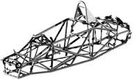
The chassis uses various types of beams or pipes are assembled into one and the construction was almost like out of the vehicle. The chassis is usually widely applied in the world of car racing, chassis type is very easy to plus or in the design and given additional reinforcement. In this type of structure is very important to make sure all areas of the pitch triangulation (try to observe the horse in a house or a bridge where all the structures created by the connection triangle model. The strength of the chassis is very dependent on the quality and the quality of welded joints of each joint.

Backbone Chassis
Understanding About the Vehicle Chassis and Body
Backbone Chassis
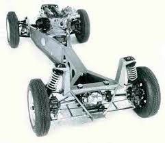
The idea was to make the front and rear structures are connected by a tube that ran along the frame of the car. Unlike the transmission of tunnels, is almost entirely backbone chassis is a rigid structure and can withstand all the loads. There are some holes continuously. Because it is so narrow walls are generally made thicker. Backbone chassis has the stiffness of parts of the backbone area itself.

Aluminium Space Frame
Understanding About the Vehicle Chassis and Body
Aluminium Space Frame
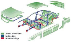
The chassis of this type were first developed by Audi car company (a subsidiary of the VW Group) together with the aluminum manufacturer Alcoa. Aluminum Chassis Frame made to replace the steel monocoque chassis due to produce a lightweight frame. It is said that the type of Aluminium Space Frame Chassis claimed 40% lighter than the steel frame monocoque but 40% more Rigid / Rigid. The picture is a picture on the chassis of the vehicle belongs to Audi.

Definition Body
Part of the vehicle body is formed in such a way (in general) is made of a metal plate (steel plate) thickness between 0.6 mm - 0.9 mm as a passenger or goods.

Automotive body construction is divided into two, namely:
1. Construction Separated (Composite)
Is a type of vehicle body construction where a separate body and chassis. Linkage / connection between the body and frame using bolts and nuts. To improve comfort during use, then between the body and frame mounted rubber as a vibration damper. Construction of a separate body and frame that provides ease of replacement of vehicle body parts were damaged, especially the lower part of the body or frame break. This construction is usually used in the old type sedan vehicles, passenger vehicles and car transportation of goods. (eg, trucks, buses, pick-ups, etc.).

2. Construction Converge (monocoque)
Construction of the body is a type of vehicle in which the body and frame are arranged into a single unit. This construction uses the principle of eggshells, which is a unified whole so that all of the load is divided evenly to all parts of the skin. The linkage between the body and frame using welding. Because the body and frame together, then the shape may be lower than the composite type so that the center of gravity lower gravity would cause the vehicle more stable. This construction is used in sedans, and even some vehicles MPV (Multi Purpose Vehicle) started implementing construction monocoq body.

Similarly, a brief review of Understanding About Vehicle Chassis and Body, hopefully what is reviewed in this article can be useful to readers, if any, need to be asked, please use the comments field.
Machine Tractor And The Work Principle
four-wheel tractor
Tractor is a vehicle specifically designed for use in high fraction purposes at low speeds, or is used to pull a trailer or instruments used in the world of agriculture or construction. The term is commonly used to define a type of vehicle in the world of agriculture. Agricultural instruments are generally driven by using this vehicle, its use can be pulled or pushed even be used to load various goods and crops and a major source of agricultural mechanization. Other general term, "tractor unit", which defines a semi-truck trailer vehicles. The word tractor was taken from Latin, meaning trahere which has an "interesting".


Tractors can be used as a power source in order to support an effective agricultural operation, good power, time and covers the costs, so as to boost the working capacity, which includes reducing production costs, improving agriculture and the findings could reduce fatigue and boredom at work.
The word tractor was originally used to shorten the explanation "a machine or a vehicle of interest gates or hijack, for the term tractor replaces the meaning of" machine puller "(trakction Engine). In the state of English, Irish, australia, india, spain, argentina, and the German state , the word "tractor" generally means "agricultural tractors", and the use of the word tractor which refers to the type of vehicle to another very rare. Instruments mechanized agriculture first steam engine portable in the Year 1800, the steam engine that can be used to control the mechanical instruments of agriculture. Around 1850, machine puller developed from the machine, and is widely used in the world of agriculture. Tractors The first is plow-engined steam. The tractor could be classified as two-wheel drive or track tractors. Tractors, except trak tracktor which generally has 4 wheels with larger wheels prayer behind or four wheels of equal size.

Track tractor has a drive like a tank that allows him to move in various fields. because traction is very great, tracktor became popular in California in 1930'an. Tractor at first using the steam engine as a primary energy source to generate power tractors. Between 1900 to 1960 gasoline has started to become the main fuel, kerosene and ethanol as an alternative fuel. Most of the old tractor wearing a manual transmission. Tractors of this type has several high speed ratio, generally 3 Up 6. Low speed is commonly used on agricultural land use, while high-speed road.
Power produced by the engine is transmitted to the equipment must be implemented to the tractor to be able to do the work required (Planting, harvesting, plowing, etc.). This can be achieved with a drawbar or connection system.

Tractor Working Principle
Machine Tractor And The Work Principle
hand tractors
The working principle is the hand tractors earth moving machines using propulsion motor fuel, which generally pang diesel motor. As an earth moving machines, tractors used to attract earth moving equipment, such as plows Dishes, Plates rakes, etc.
While the Four Wheel Tractor operated by the operator sitting in the control while sitting while driving. Earth moving equipment attached or connected to the tractor through a device called three hitch points or connecting three dots, which consists of a pair of forks left and right, while the one lever the other is at the top of the system connecting three dots, called the top link (lever connecting the top ).
By using this splicing system position control equipment (such as plowing, etc.) That can be set by the operator wants to lengthen or shorten the upper connective lever. To secure that the tractor was not raised at the time of operation for land preparation work, the tractor needs to be balanced with the load when installing an additional burden on the front of the tractor. By doing this kind of preparation, the preparation of tired tractor ready to be operated in the processing of the soil.
Some of these things need to be considered when going to use four-wheel tractors in tillage:

  • Adjust the angle of the plow position (other devices) to the soil surface adapted to soil conditions (heavy or light soil).
  • Plow angle position adjustment is done via a lever connecting the three points.
  • Attach the load as a counterweight at the front of the tractor.
  • Tractor ready to operate for a job in cultivating the land.


Requirements Tool
Terms of Use of this equipment include:

  • Load drawn (plows, harrows, rotary, carts) are still within the limits of the appeal of the tractor.
  • Adjust the type of wheel used by the operating requirements in the field.
  • To Tilth in the paddy field, use the wheel cage, whereas for use on dry land or in road transport activities can be used for tire rubber.


Usefulness Tool
Usefulness of hand tractors in agriculture are:
To attract the earth moving equipment such as plow, rotary plow and harrow, also means of transport such as carts to move the stationary equipment, such as power plants, water pumps, rice milling machine, etc.

Completeness Tool
Hand tractors as the main part of the earth moving machine to be equipped with tools that support the cultivation of land, such as plows and harrows. Without these supplies on hand tractors merely act as a tool or machine towing equipment. Some fittings are required, among others:

  • Processing plow is a tool to first land could serve to reverse the sliced ​​surface.
  • Rotary plow or plow claw cultivator is a tool that serves cutting and stirring the soil, so the soil processed results being crushed or muddy.
  • Garu is a second ground processing tool that serves to crush and flatten the ground.
  • Wheel cage is a type of wheel made of iron pipes and plates shaped like a cage. Cage wheel function is to increase the traction surface of the wheels against the ground, thus the occurrence of slippage can be overcome.
  • Rubber tire wheel is a type of tire rubber that serves to support the operation of the tractor on dry land and support in road transport.

While the four-wheel tractor is a machine that functions as for driving or towing equipment. To be used as a soil processing machine, it Must be equipped with earth moving equipment, such as plow, plow plate, rakes Plates, atomizer pests and plant diseases, etc.
Four-wheel tractors treatment should be done regularly and caregivers need to recognize parts tractor parts and their functions. Four-wheel tractor specification varies depending on the magnitude of the driving force, tire size, attractiveness, lift, gear, etc.
The main parts of the four-wheel tractor has a function, respectively, among others:

  • Steering system: a tool for use in controlling the course or tractor operation in the Field.
  • Front wheels: the front wheels of the tractor that serves as a control, and has ukura smaller diameter than the rear wheels.
  • The rear wheels with a diameter larger than the front wheels of tractor which serves rivet load tractor and attached equipment.
  • Tractor chassis: The frame four-wheel tractor that also doubles as the home of the transmission system.
  • Ballast: The cast iron which is specifically designed to be a ballast tractor that was not raised at the time of tilling the soil.
  • PTO shaft: shaft are enabled to be able to move the equipment in operation requires rotation (rotary plow), or it can be to move the stationary equipment.
  • Splicing system equipment: Shape ground processing equipment is relatively large, then the four-wheel tractors require special splicing mechanism, the system connecting the three point (three-point hitch).

Entering the era of high technology such as current use agricultural equipment with modern machinery that helps speed up the processing of agricultural production. One of the tools are common and most often used is the tractor, be it hand tractors and four-wheel tractor. Tractor engine is a tool that has the ability to be able to cultivate the land. Function tractor now replace the power function of animals such as cattle and buffalo in the processing of land, although there are those who still use animal power. A good introduction on this tractor engine, can speed up the process of agricultural modernization.

Thus a brief description of the article on the tractor and its working principle in the world of agriculture, hopefully what is presented in this article can be useful more particularly for farmers, and do not forget to share this article that could be useful for other readers.


WORK SYSTEM LATHE


Understanding Lathe

Lathe is a machine tool used to cut the object is rotated. Lathe itself is a process that feeds the workpiece incision done by rotating the workpiece is then imposed on the chisel driven translational parallel to the spin axis of the workpiece. Rotary movement of the workpiece relative called cut motion and translational motion of the chisel is called motion decoy.

By regulating the ratio of the speed of rotation of the workpiece and the speed of translational chisel it will obtain a wide range of coarse thread with different sizes. This can be done by way of swapping gears translational spindle shaft that connects with the screw shaft.

Gear changers reserved exclusively to fulfill the purposes of making a screw. The number of teeth on each gear changers varying magnitude ranging from number 15 up to a maximum of 127. The number of teeth gears exchanger with the number 127 has specificity because it is used for the conversion from metric screw threaded into inches.

Working Principle Lathe

The working principle lathe is actually located on the workpiece. The round will be aligned with the spin axis of the workpiece, the lathe is used to cut an object will perform translational movement parallel on the lathe chisel. because the sculpture to adjust the axis of rotation of an object, then the results of the lathe will be in the form of a screw. The workings of the lathe is that by regulating the ratio of the rotational speed and rotational speed sculptured objects. If you are able to adjust the speed of the two, then you will get the kind of - kind of thread which have different sizes - different.

in principle described lathes, lathes can get a helix that is wide - range of different sizes - thanks to the different parts of lathe named gear translation. The gears that make up a screw - threaded on a timber or object. In order to get a thread of different sizes - different, you just need to swap gears translational who serves as a liaison between the spindle shaft and screw shaft. You should know it turns out the number of teeth on the gear changers are different - different, ranging from 15 teeth to 127 teeth. So do not be surprised if you could have a wood screw to the size of the different - different.

In addition to the working principle of the lathe also explained how to get a thread on the object. First, the spindle axis will rotate the workpiece, the disc was Black who exploited by the spindle shaft when rotating the object in his hand. Besides disc was Black who succeeded in turning the gear on the spindle shaft. Round will be delivered to gear screw shaft through a gear linkage, then by the rotation of the screw shaft is converted by the clamp screw into the translational motion on the sled that carries the chisel. The translational motion produces a screw-shaped incision on an object.

a lathe will not work optimally if the parts - no part of this machine. Part - part of lathe including:

The main axis
Serves as the laying of the object at the time turner, the main axis there is also a permanent center and dibble containing gears.

Sledge
Functioning emphasis on objects that emphasis can be set as desired operator.

Head off
Serves as a center turning lathe is a support device.

Lever
Serves to regulate the speed of the shaft and the axis of the carrier.

Reversing lever
Serves to reverse the main axis rotation when making screw.

Clamp Sculpture
Functioning pinning some chisel.

Top sledge
Serves to adjust the chisel when used for mengulir an object.

Kran Cooling
Serves to cool the cutting tool when turning an object.

Players wheel
Serves to move the spindle head back and forth.

Transporter
Function automatically brings sledding.

-the Other parts of the machine that is the carrier axis, lever linkage, sleigh latitude, speed tables plate and others - others.

By knowing the parts - part of lathe you can better understand the working principle of a lathe, and hopefully the information about the part - lathe machine parts and function may help you in understanding the workings and the working principle of the lathe.

Thus I can tell, may be useful.

Read also the article on:
Stamping Process
Grinding machines
cnc machine

SURFACE GRINDING MACHINE


a. Definition
Surface Grinding machine is a grinding machine which refers to the manufacture of flat shape and a flat surface on a workpiece under a rotating grindstone. Surface grinding machine can be encountered in ATMI on Brand and Magerle machine. In general, grinding machines are used for grinding the surface of the machine table moves horizontally back and forth. Workpiece gripped on the magnetic table, driven back and forth under a millstone. Table on flat grinding machine can be operated manually or automatically which can be arranged on the lever.

b. Classification
Surface grinding machine based on the movement of the table and spindlenya divided into four kinds, namely:

1. flat horizontal grinding machines with alternating motion table
The grinding machine used to grind objects with flat and angled surfaces. Regarding the step length on the table and the transverse movement of the grinding stone can be set on the table lever grinding machine according to the nature and character of the workpiece to be done.

2. flat horizontal grinding machine with rotating table motion
This type of machine is used for grinding flat surfaces on cylindrical workpieces. Precisely section of the flat surface of the workpiece with a turning movement table surface grinding machine.

3. flat vertical grinding machines with alternating motion table
This type of machine is used to grind the surface of objects flat, wide and angled. Grinding takes place on the side of the grinding wheel so that when the process must be careful in feeds (DOC) by way of a more piecemeal. How this is done so that the workpiece does not burn when receiving a load and cross-sectional area is too large on the side of the grinding stone pieces.

4. flat vertical grinding machine with rotating table motion
This type of machine is used for grinding the flat surface of the shaft and the hole. Can also to make precise holes if there is no universal grinding machine in your garage when the need for such grinding holes in the image opposite.

Based on the principle works flat grinding machines are divided into two kinds, namely:
1. Surface grinding semi-automatic, the cutting process can be done manually (hand) and the automated machine.
2. Surface grinding automatic cutting process is set through the program (NC / CNC Numerical Control and / Computer Numerically Control).
Based on the principle of cooling (coolant) flat grinding machines are divided into two kinds, namely:
Dry grinding
In accordance with its objectives, dry grinding is done without using coolant. So that dust arising from the grinding does not fly and inhaled by people working, the machine is equipped with a vacuum cleaner. Because if not vacuumed, the dust will settle on engine parts.
Wet grinding
In the wet grinding coolant used to prevent dust arising from grinding. This needs to be maintained in order not to involve the operator, nor strewn out the engine and hit the floor. Therefore this machine needs to be equipped shield to withstand the cooling fluid. In the wet grinding, we can maintain the properties of the metal, because the temperature did not rise due to friction in the cutting process.
The main working principle of surface grinding machine is a back and forth movement of the workpiece, and the rotational motion of the tool. Judging from the main working principle of these machines, grinding machines flat in outline has three major movements, namely:
1) Motion rotary grinding stone.
2) Move the table lengthwise and crosswise.
3) Motion feeds

c. Various clamping on surface grinding machine
1. Tables electric magnet
This clamping is most often used most of the surface grinding machine. Thin workpieces that are not able to be done on a regular clamping chuck is suitable for this. Clamping occurs due to the magnetic field generated by the flow of electricity. On the flat grinding machine that serves as clamp workpiece is a grinding machine table itself. Workpiece clamping process using an electric magnet table, must have a condition that the surface is cleaned and magnet magnet table in the on position. The workpiece is placed on the surface of the magnet table and set to work the magnetic field lines. Of course, the workpiece should be in pristine condition as well. Clamping using electromagnetic principles. Bars which in the end is set so as to produce a magnetic north and south poles alternately when electrified. So that the flow of the magnetic field passing through the workpiece used nonferro metal plate inserted on top of clamping magnet. When removing the workpiece is done with a cut off electricity to the magnet clamping using on / off button.
2. Table of permanent magnets
Clamping occurs due to the permanent magnets contained in clamp. In the grinding machine of this type, which flow through the magnet is a permanent table, workpiece clamping process using a machine equipped with this type of table is similar to the process of clamping the workpiece on a flat grinding machines in general. However, there are several things that distinguish this type of machine with a grinding machine in general.

The difference is as follows.
a. This theory just as magnetic that are in Stand Dial indicator. 2 mengadung magnetic poles work and when there are two different poles brought near (north-south), 2 poles do not work if there are two similar poles brought closer.
b. The difference lies in the magnetic source that has been owned, without using a flow of electrical current (permanent magnet plates).
b. Permanent magnet plates located between the metal anti magnets mounted between the upper and lower plates.
c. Top plate has a plate inserts anti magnet which serves to direct the flow of the magnetic field.
d. Lever position "ON", the position of a piece with pole magnet plate inserts in the upper plate. The magnetic field flows from the south pole to the outside pole (upper plate) and passes the workpiece is forwarded to the north pole and the bottom plate so that the workpiece to be gripped.
e. The workpiece is set to the work flow of the magnetic field lines contained in dibble magnet.
f. Lever position "OFF", the flow of the magnet is moved as the magnetic plates and inserts are not collinear magnetic fields of work flow. Upper plate and inserts will cover the flow toward the workpiece so that the workpiece is not gripped.
3. Swivel vice
Used when the workpiece clamping that all areas have been grinded, where between one another perpendicular and parallel. The workpiece clamping process using this vice as follows.
· The surface of the workpiece is clamped by the vice produces grinded field that will have a good elbow and alignment with the proviso vice already configured elbow and flat.
· Vice gripped by using a dibble magnet in position can be changed change according to the desired grinding. Fields of vice is used as a base and retaining field.
· Surface clamping field and seized must be clean of impurities that interfere clamping and precision grinding.
· To grind the workpiece perpendicular, vice rotated 90 ° without having to open the clamping workpieces, on condition that the workpiece surface is higher than the surface of the vise jaws. For another angle can also be done by setting the position of the workpiece before using bevel transfer that has been set on the bevel protactor.
3. Table sinus
Sine table can be used for gripping the workpiece in grinding at an angle to achieve precision angular unit in seconds,

The clamping process the workpiece with the vise sinus as follows.
· The table is gripped in a magnetic table (the table surface sinus also contain magnets that are useful to put the workpiece at the top).
· The slope of the desired angle is set to loosen a key that is usually tuned by L. Then the key is positioned at the desired angle and then tightened again.
· The workpiece is mounted on top of the table sine field with magnetic table clamping system as well.
4. The sine table universal
No doubt that the workpiece has a complex shape. It depends on factors such workpieces with a partner later when dissembling. To measure that has a slope demands, this table is very suitable for clamping. Universal sine table is used to form an angle toward the vertical and horizontal direction. Serves to continue the flow of the magnetic field of the magnetic source to the workpiece. There are three standard forms of conductive blocks, namely a square, triangular and V groove, or Block V. each axis has angle information so that we can twirling this table.
Block V square block

5. The special clamping
· Block conductor magnetic field (layered packing), used for gripping workpieces do not allow gripped directly on the magnet table.
· Block conductor magnetic field grooved V, used for gripping workpieces angled with special angle.

d. Parts of Main Machine Surface Grinding

Column
This section serves to prop up the grinding head unit.

Reversing Direction lever Desk
serves to reverse the direction of motion slicing table. Equipped with a stopper as limit the movement of the table surface grinding machine.

Handle Aft
serves to move the table with the lengthwise direction can be set stride length.

Handle Transverse
serves to counter the transverse direction can be set stride length.

Control Box
Wherein lies the control buttons are in use as a machine control center.

Coolant Box
Place the coolant. This place must often in check as if to negligence can make the chip in the form of powder settles and can hinder circulation of coolant.

Alas Machine
Alas machine bed is also called a box made of cast iron and placed inside the hydraulic drive unit. At the top of the bed there is a V-shaped groove as a sleigh gliding.

Sledge
Sledge called the saddle. Sledge moves back and forth in a longitudinal or transverse direction above the bed.

Table
This table is attached to the upper surface of the carriage. Equipment workbench equipped with three grooves T to place a bolt fastener. Table surface grinding machine with precision when assembled. On the table can be placed magnet for gripping workpieces.

Grinding head
Grinding head unit is made of cast iron, in which there is the axis of the grinding wheel and the retaining friction of bullets. Axis or grinding shaft made of alloy steel and grinded precision. At one end of the axis of a motor or pulleys attached.


e. Workpieces produced
Sample results from surface grinding machine is Parallel block, V-Block, Caliper, Bed Machine, etc.

STAMPING PROCESS


A. Definition Stamping Process
       The stamping process is as cold metal molding process using dies and press machines generally plate printed, to produce in accordance with the desired product diemold's blog. accessed from.

B. - things that need to be considered in Stamping Process
1. If Dies too large, the engine used less tonnage, inadequate, not thinking of the safety factor, will cause the machine easily damaged, especially on the bearings and crankshaft, as well as the motor may burn due to over load.
2. If the stroke setting is too high, the resulting product is not good reject.
3. If the stroke is too low will cause the upper die and lower die collision, the dies can be broken.
4. If the upper die and lower die due slider stroke centers not worn (already hilarious), then the resulting product is not good reject.
5. If the guide post and guide bush is worn or not center, products are not good.
6. If the blanking clearance between the upper die and lower die, too little can lead to die during stamping can not be opened, or it could also die quickly wear out, If the clearance is too large will rapidly cause bari.
7. If the hardening die die fragile too hard, too soft when hardening die die easy to wear.
8. If the election material was not good die, die quickly broken.
9. If the material thickness tolerance pressed too high will cause rapid deterioration die. The product is not good.
10. If the material hardness unstable pressed, will cause the die easily damaged, and the product is not good.
11. If the bearing is worn bearing in the machine, especially on the parts related to stroke, Die can be easily damaged, or the product is not good.
12. If the design of die lack expertise, in terms of the design of die, then maybe the die will be broken, the product is not good.
13. If the components die of components with low quality of, will cause rapid deterioration die, the product is not good.


C. Kinds - kinds of Stamping Process
       In general, the processes contained in the stamping process is grouped into three parts:
1. Cutting Process (cutting).
       The cutting process is a process where material is cut according to the desired size so that the material can be worked into the next process. Type - the type of cutting processes, among others:
a. Blanking
Blanking is the process of preparing the material, the material is cut as required. Blanking process aims to get the piece or blank, while the rest will be disposed of as garbage or so-called scrap.
b. Cutting
That is a process that is still shaped cutting sheet material (blank material). The cutting process is the process of cutting some part of a part. The rest of the cuts discarded as scrap.
c. Trimming
That is a process of cutting the material at the edges. Usually this process is a continuation of previous processes such as draw, stamp and so on.


b. Notching.
Notching is on the edge of the cutting process the material part, usually on progressive dies. With these cuts, part gradually formed while still attached to the scrap skeleton.
c. Parting or Separating
Parting or separating is the process of separating a part into two parts or multiple parts from sheet metal strip so as to produce the desired part. In the process of separating scrap are unused.

2. Forming Processes (formation).
       Forming is a general term that is used in sheet metal forming process to obtain the desired contour. Forming process, not result in a reduction or removal of material as happens in the cutting process. So to term formation also vary so that no misunderstanding. The types of forming processes include:
a. Bending
       Bending is a process of bending the plate where the results of this bending a line in accordance with the form of the desired angle.
b. Flanging.
       Flanging is the same as bending but the resulting bending lines are not straight but follow the shape of the part in question. This process is intended to strengthen the sides of the product or to reason, beauty.
c. Forming.
       Forming refers to a more narrow sense which means it is the deformation of sheet metal that is a combination of bending and flanging process. Forming process produces highly complex shapes by bending-bending and complicated contour parts.
d. Drawing.
       Drawing is forming deep enough so that the formation process requires a blank holder or stripper and water cushion / spring to control the flow of material. For irregular shapes bead necessary to balance material flow. To produce a good product, you should use a special steel sheet drawing process and use hydraulic press machine.
e. Deep Drawing.
       Deep Drawing a deep drawing process so as to get the shape and size of the final product required several times a drawing process. Blank holder / stripper absolutely necessary and can only be processed on hydraulic press machine and uses a special metal sheet for deep drawing.

3. Process Compression (emphasis added).
       This process includes the forming operation in which a strong emphasis is given to the sheet metal to produce a high compression stress on the plate to produce plastic deformation. Types of emphasis process are:
a. Stamping or Marking.
        Marking or stamping or sometimes called coining process is used to make signs, symbols, letters or other forms of cold forging process.
b. Heading.
      Heading is the process of formation of the head part, usually on steel material bar. Forming process with the process of hot forging or cold forging where the ends of the parts are processed using the pressing dies to form the head.
c. Sizing.
       Sizing is an operation in which the plate material given the high pressure which causes the material to flow, therefore sizing aims to increase the dimensional accuracy of the part / workpiece.

D. Tool - Supporting tools Stamping Machine.
       In addition to the press machine Stamping Process in conducting production also requires a tool - a tool to support the pressing To produce good quality.
Support tools press machines, among others:
1. Dies
       Dies is a mold that is driven by a pressing machine for pressing or pressing / material to produce goods in accordance with the example. Dies materials used are: general, special stainless alloy, which can be done hardening process to HRC hardness above 60, for example: DC 53, SKD 11, etc. There are some parts that are important dies: For example cavity, Guide Post, Upper plate Lower Plate.
In general, dies construction is divided into two parts, namely:
a. Single Operation Dies.
Single Operation Dies or so-called single dies is the construction of dies that have a process on its die set and only produce a part in one stroke. Part produced can be a result of blank, part of semi-finished or finished goods part.
Kind of - kind of a single operation dies, among others:
1) Cut Off Die.
       Cut off used only for the die cutting process with the aim of cutting blanks, separating or cutting scrap. Cut off the die is also often combined with a blanking process for cutting scrap. Cutting blank with die cut-off is limited to a simple blank and accuracy are required.
2) Cut Off and Drop Through Blanking Die.
       Cut Off and Drop Through Blanking Die blanks used for the process of cutting, only the results of the cuts will fall to the bottom of the die passes through a hole in the engine bolsters and into shelters. Cut off very efficient in the use of materials as scrap is wasted very little.
3) Drop Through Die.
       Drop Through Die or with other terms Through Die Blank is the construction of press dies whose products fall to the bottom of the die and passing through the hole on the machine bolsters and into shelters. Construction dies like this in general for blanking process and to dispose of scrap in the process pierching. For this type of construction requires stripper dies to hold the material when the dies are at work. Inverted Die or other terms of Return-Type Blanking Die is die blank where the results would fall to the bottom die, but returned to the top in the same position during cutting. This mechanism may occur due to the lifting pad back blank results because of the force that presses spring or urethane pad upwards. Sometimes the arrangement of the punch and die reversed by putting the punch down and die on top, with a blank thus produced will be above that then the knockout mechanism.
b. Multi Operation Dies.
       Multi Operation dies Dies are designed to work on two or more operations in one stroke. Construction dies because it is more difficult to look for height 4 die suitability of these processes. If the height of his die is not the same then the resulting part is not in accordance with the desired specifications of the product drawing. Various multi operation dies are:
1) Compound Dies.
       Compound Dies is a combination of two or more processes related to one means two or more processes are designed on the one dies. The time the process is carried out simultaneously. Option to create a compound dies depends on several considerations, among others:
a) Cost of production
b) Cycle time is short
c) Accuracy part
d) saving machine usage

2) Combination Dies.
       Combination Dies or a term commonly called Group Tool, Process Gang or Family Dies which means it is a combination of two or more processes on a single die sets which are not parallel use. This means that on a single die set there are two or more processes. In one stroke resulting number of parts corresponding to the number of existing processes on a single die set.

3) Progressive Dies.
       Progressive process: The process of printing / stamping is done all in one process dies. The whole process is done in one dies, so that once printed the final product has been directly obtained. Progressive Dies consists of multiple processes or multiple station interconnected originating from the same material. In the progressive dies generally use coil (steel sheet coils) and a coil feeder as a driver coil automatically. Part processed from the beginning will continue on a sheet attached to the plate until the last process. Prices progressive dies are very expensive, therefore only products that are high-volume production using press dies of this kind.

2. Press Machine.
       Press machine is a machine that carry the a foundation and a pestle, a power source, and a mechanism that causes pounder moving straight and upright toward the foundation. Press machine itself many kinds, the most important to the press machine is a precision stroke and tonnage capacity, the capacity of the smallest tonnage of under 1 ton up to the largest hundreds if there are thousands of tons. A small capacity of course for a small product, the greater the greater the products that can be made.
Kind of - kind of press machine, among others:
a. Machine O.B.I. Prees
       One press machine that is often found in the market is OBI Press (Open-Back Inclunable, Punch Press).
When we see O.B.I. pangerjaan press suitable for stamping, blanking, forming, drawing, perforating (hollow), embossed, coining, coining, notching, bending, shearing (cutting).
Variable speed motor depending on the engine. To change the speed required in accordance penggentian pully speed of movement required.
b. GAP machine Press.
       GAP Press has a full body that handles workmanship plate keras.Alat length and width, and also provide space around the dies. GAP Press commonly used for regular stamping.
c. Horning Press.
       Horning press cylinder used on objects. Used for seaming (seam), puncing, embosing. This machine is equipped heading wide in the bed .Beban imposed in dies vertically. The voltage received by the side frame. But in fact occurred small tendency to punch and die. In the press machine of this type was different ways to run the operation of RAM. Single crank generally only able to be used on light suppression. Heavy construction added to the crankshaft to distribute the load evenly on the slide.
d. Hydraulic machines Prees.
       Hydraulic press used specifically for the working drawing because its operation is slow so it is not suitable for production activities. Hydraulic press was made for the operation of such deed - draw forming, straightening, plastic molding, dic spotting, and powered compacting metal. This machine can not be used on heavy construction blanking and punching ..
e. Machine Turret Press.
       Press turret machine consists of upper and lower turret carrier, which brings punches and dies with varying sizes. Beater (punches) directly above and below it there dies. This machine can make a hole that size varies. Turret punch press with varying tape controller is available in 15-150 ton capacity. Numerical - positioing control can make 65 holes per minute with an accuracy of ± 0.004 ".
d. High machine - Production Press Transfer and Others.
Press transfer machine for the production work such as ice cube trays (a tray of ice cubes), the oil, and the house lights of vehicles with the average - average 500-1500 pieces per minute. The way it works is: the material is inserted in the machine of rools, then moved from one position to the next by working mechanism.
e. Machine Press Brake.
       brake press machine which is set to form the curve and shape the metal, which can handle sheet width and can accommodate multiple dies (grounding). This particular type of engine to elongate, bent straight. Brake press machine is ideally used for Corrugating work, seaming, notching, embossing, wiring, or curling and forming cylindrical tube tapers.
f. Machine Shears (Scissors).
Machine shears (scissors) are classified as follows:
1) The cutter blades (blade shear).
2) billets, or scissors structure.
3) Nibbler.
       This machine is designed for cutting metal with a knife to cut the sheet - the sheet plate. Knives be operated by foot pedals, fingers hold the plate to be cut. Before cutting plate specify the cutting line, when it is appropriate, press the pedal.
3. Material plate
       The materials used for this stamping process generally is a material that has a low hardness, can also be said material class low carbon steel, low carbon steel material group is easily bent, pressed, and molded. Examples widely used are: SS41P.

Bibliography :
Rony Sudarmawan Theryo, "Press Dies Maintenance", Astra Manufacturing Polytechnic.

Hilman, Azmi. Design and Analysis of Stamping Dies Bumper Bracket for Product Development Process With Multi Forging Press. FTIUG, Depok, 2005.
Subscribe to RSS Feed Follow me on Twitter!